Lightbox
Making a LED blink using an Arduino is easy. But how about creating an analog system that blinks a LED in a range of frequencies and durations, while not using any microcontroller, and needing to design a PCB, a 3d-printed box, and adhere to other very specific constraints? Well, I guess you can say that it was a box of surprises.
Background: Thanks for reading through the pun above. As it describes actually really well, this project was a challenge designed by my Medical Device Design professor to help us practice important skills and go through the whole product development cycle. The specific constraints and tight timeline are just 2 examples of all of the things we had to consider and go through in this project. It was a great learning experience!
Specifications:
SPST switch to turn device on/off.
Press button that initates a 10 Hz, 50% duty cycle blink
SPST switch to turn device on/off.
Press button that initiates a 10 Hz, 50% duty cycle blink of an LED for 50 on/off cycles. The LED is otherwise “off”.
Powered using voltage-regulated, 9 V battery, with reverse-polarity protection.
Battery must be replaceable in under 5 min.
Battery life ≥ 4 hours.
Single-sided printed circuit board.
Weight ≤ 0.5 lbAll dimensions < 4 in (including protruding switches, LEDs, etc.)
Enclosure is “sealed” / air gaps minimized
≤ $20 to duplicate unit (i.e., no microcontroller)
Survive 3 ft drop
Secure mounting of all internal components
Fillet corners / edges
Reduce protruding switches, knobs, etc.
Safe
Extra Credit
Add a rotary knob that modulates the total number of LED blinks associated with a button press.
Add a rotary knob that modulates the frequency of the LED blinking (the duty cycle is allowed to deviate from 50%).
Results:
My circuit schematic:

My PCB design:

My soldered components:

The design of my enclosure:

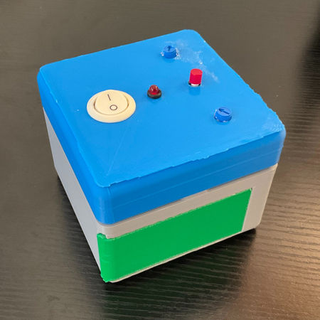
And this is the final product!


And to prove the correct electrical output, here is a screenshot of the oscilloscope used for testing:

While it was not perfectly on point with the values above, it was within the allowed error threshold and worked well! It was great to see it working!!
Takeaway: This was a very instructive experience! It was great to go through the whole product development cycle with specific requirements and instructions. I also learned a lot from methodical testing and troubleshooting. I spent many long afternoons and nights in the lab troubleshooting my PCB that had some mistakes that I did while designing it. While it was demanding, I learned a lot from it! I now embrace and actually enjoy troubleshooting much more!
Project Gallery


